
-560x560.png)

Automated Machining Solution for Bearing Rings
VTD300 Automated Processing Solution for Bearing Rings
High Precision, High Efficiency — Preferred Equipment for Automated Bearing Ring Processing
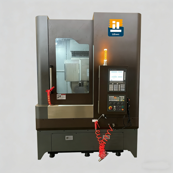
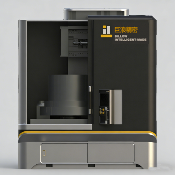
I. Product Information
1.1 Product Drawing
This solution uses this product processing as an example

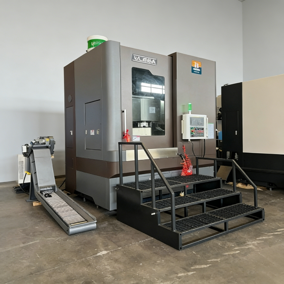
II. Automated Production Line Layout
2.1 Layout Introduction

2.2 Layout Dimensions

III. Automated Components
3.1 Roller Conveyor Line

Blank Placement Schematic | HMI Panel
Technical Description
1. Roller conveyor line is used for product transportation based on product shape, with large load-bearing capacity and strong adaptability.
2. Safety protection: When a single or multiple rollers are under force (e.g., manual pressing), the affected roller(s) can stop independently without affecting other rollers.
3.2 Transplanting Mechanism

X-Axis | Z-Axis | Gripper Schematic
Technical Description
1. Two-axis moving module for product docking and conveying, both axes driven by servo motors to ensure pick-and-place accuracy.
2. Three-jaw cylinder internal gripping method, with copper inserts on jaw fingers to prevent scratching of product inner surface.
3.3 Loading/Unloading Mechanism

Blank Placement Station | Finished Product Station | Machine Internal Loading/Unloading Schematic
Technical Description
1. Single-rail moving mechanism inside the machine, designed with two stations for one-pick-one-place process, ensuring non-stop operation.
2. Power transmission uses servo motor + ball screw + linear guide to ensure machine pick-and-place accuracy.
3.4 Flipping Mechanism

Flipping Mechanism | Blank Conveying Direction | Finished Product Conveying Direction
Function Description
Implements automated processing flow from OP10 to OP20.
Automatically completes workpiece flipping, ensuring continuous processing across two operations, improving production efficiency.
3.5 Supply List
| Name | Quantity | Origin | Remarks |
|---|---|---|---|
| CNC Vertical Lathe | 2 Units | China | Automatic Side Door |
| Roller Conveyor Line | 3 Lines | China | |
| Transplanting Mechanism | 2 Sets | China | |
| Loading/Unloading Mechanism | 2 Sets | China | |
| Flipping Mechanism | 1 Set | China | |
| Safety Fence | 1 Set | China | With Two Maintenance Doors |